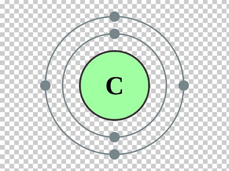
Also shown are the outer electrons ( valence electrons) on the outermost main shell ( valence shell), since these are decisive for the chemical behavior of an element. The subshells belonging to a main shell are all marked in a uniform color. Note that the number of electrons increases to the same extent as the number of protons and thus increases by one from element to element. The animation below shows the electron configuration with increasing atomic number of the atoms. Figure: Aufbau principle (occupation order of the orbitals) This principle is also knows as the aufbau principle (“Aufbau” is a german word which means “configuration”). The energetic order of the orbitals can now be obtained by going through the table diagonally line by line from top right to bottom left. Thus, the subshell with associated main shell is clearly defined for each field.

Therein, the line numbering corresponds to the main shell number and the column numbering corresponds to the subshell. In order to better remember the energetic order of the orbitals, you can first create a table. The subshells are divided into white-framed blocks, each providing space for a total of two electrons. The energetic distribution of the shells is shown in the figure above. Instead atomic orbitals are used, which will not be discussed further here. Here, a subshell of a lower main shell number may well have a higher energy level than the subshell of a higher shell number (Sommerfeld explained this with elliptical orbits of electrons instead of circular orbits after Bohr)! For example, the subshell 3d has a higher energy state than the subshell 4s! The graphical representation by shells with their subdivisions in subshells is therefore no longer possible.

The shell designation 2d, however, does not exist because the second main shell has only one s and one p subshell! Subshells can only be occupied by a certain number of electrons: A g-subshell exists only for theoretical elements with atomic numbers greater than 121 (called superactinoids), which is why this orbital has only theoretical meaning.ġ th main shell (K): 1 lower shell (s), identical to the main shellĢ nd main shell (L): 2 lower shells (s, p)ģ rd main shell (M): 3 lower shells (s, p, d)Ĥ th main shell (N): 4 lower shells (s, p, d, f)įor example, the shell designation 3p means the subshell p (“2nd subshell”) of the third main shell and the designation 4s the subshell s (“1st subshell”) of the fourth main shell. The lower shells are not labeled with numbers but with lowercase letters (s, p, d and f). In the figure above, not all subshells of the higher main shells are shown, as these usually have no relevance. The number of the main shell indicates the number of subshells.

The number of subshells depends on the main shell. One imagines the main shells introduced by Bohr subdivided into subshells. Figure: Electron configuration of elements It will be explained in more detail below. The distribution of electrons in an atom is referred to as electron configuration. With the introduction of these subshells, it was finally possible to explain the distribution of the electrons within the shells. In addition to the already introduced shells by Bohr, Sommerfeld further introduced subshells (also referred to as orbitals).

The weaknesses of the Bohr model could be partially eliminated by the physicist Arnold Sommerfeld. It explains the distribution of electrons within the shells. The Bohr-Sommerfeld model is an extension of the Bohr model.


 0 kommentar(er)
